Arduino, C, and more
Our chip today: AT SAMD11C

Our chip today: ATtiny1614
- Small: 14 pins
- Cheap: ~0.6€
- Same family as most Arduino chips, AVR manufactured by Microchip formerly Atmel.

The Arduino abstraction
```
void setup() {
pinMode(7, OUTPUT);
}
void loop() {
digitalWrite(7, HIGH);
delay(1000);
digitalWrite(7, LOW);
delay(1000);
}
```
Note
Program it with:
python pyupdi.py -d tiny1614 -c /dev/cu.usbserial-FTDIPORT -b 115200 -f 'hexfile.hex' -v

The “real” thing
Let’s look at the datasheet ATtiny1614 Datasheet

Memory

Registers

What is a byte?
| Length | Name | Example |
|---|---|---|
| 1 | Bit | 0 |
| 8 | Byte | 10110101 |
Let’s think on them as collection of 8 switches:

Addressing registers
- PORTx.DIR register: Configures pins as input or output Do we want the pin for a button or an led? (1=OUTPUT and 0=INPUT)
- PORTx.IN register: Read data from pins Is the button pressed or not? (1=HIGH and 0=LOW)
- PORTx.OUT register: Write data to pins Turn on or off the led. (1=HIGH and 0=LOW, on INPUT pins 1=PULLUP)
Test this with your Arduino IDE as before:
```
void setup() {
PORTB.DIR = 0b00000001;
}
void loop() {
PORTB.OUT = 0b00000001;
delay(1000);
PORTB.OUT = 0b00000000;
delay(1000);
}
```
Now, let’s do the examples using plain AVR C as on the FabAcademy examples:
```
include 
define F_CPU 3333333 /* 20MHz / 6(default prescale) */
include 
int main(void) {
PORTB.DIR = 0b00000001;
while (1) {
PORTB.OUT = 0b00000001;
_delay_ms(1000);

PORTB.OUT = 0b00000000;
_delay_ms(1000);
} } ```
Bits manipulation
Bit manipulation is the act of algorithmically manipulating bits or other pieces of data shorter than a word. In digital computer programming, a bitwise operation operates on one or more bit patterns or binary numerals at the level of their individual bits. Wikipedia
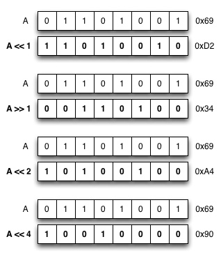
Bit Shifting
``` 1<<1 = 0b00000001 1<<2 = 0b00000010 1<<3 = 0b00000100 …
1<<6 = 0b01000000
```
Bit Masking
PORTA = 0b00000000;
OR operation:
``` 0b01000000 <= (1<<6) 0b00000000 <= PORTA
0b01000000 <= PORTA ```
PORTA = 0b01000000;
PORTA = (1 << 6) | PORTA
```
include 
define F_CPU 3333333 /* 20MHz / 6(default prescale) */
include 
int main(void) {
PORTB.DIR = (1 << 0) | PORTB.DIR;
while (1) {
PORTB.OUT = (1 << 0) | PORTB.OUT;
_delay_ms(1000);

PORTB.OUT = ~(1 << 0) & PORTB.OUT;
_delay_ms(1000);
} } ```
Macros
In the C preprocessor a macro is a fragment of code which has been given a name. Whenever the name is used, it is replaced by the contents of the macro.
```
define rocketscience 6
digitalWrite(rocketscience, HIGH); ```
Is the same as this:
digitalWrite(6, HIGH);
Let’s turn our bit masks in to macros:
```
include 
define F_CPU 3333333 /* 20MHz / 6(default prescale) */
include 
define pinOutput(port, pin) (port = (1 << pin) | port)
define digitalWriteHigh(port, pin) (port = (1 << pin) | port)
define digitalWriteLow(port, pin) (port =~(1 << pin) & port)
int main(void) {
pinOutput(PORTB.DIR, 0);

while (1) {

  digitalWriteHigh(PORTB.OUT, 0);
  _delay_ms(1000);

  digitalWriteLow(PORTB.OUT, 0);
  _delay_ms(1000);

}
} ```
Let’s turn our Macros in to Neil’s style macros. First just the functions:
```
include 
define F_CPU 3333333 /* 20MHz / 6(default prescale) */
include 
define output(directions,pin) (directions |= pin)
define set(port,pin) (port |= pin)
define clear(port,pin) (port &= (~pin))
int main(void) {
output(PORTB.DIR, 1 << 0);

while (1) {

  set(PORTB.OUT, 1 << 0);
  _delay_ms(1000);

  clear(PORTB.OUT, 1 << 0);
  _delay_ms(1000);

}
} ```
And then the pins names also:
```
include 
define F_CPU 3333333 /* 20MHz / 6(default prescale) */
include 
define output(directions,pin) (directions |= pin)
define set(port,pin) (port |= pin)
define clear(port,pin) (port &= (~pin))
define output_port PORTB.OUT
define output_direction PORTB.DIR
define output_pin (1 << 0)
int main(void) {
output(output_direction, output_pin);

while (1) {

  set(output_port, output_pin);
  _delay_ms(1000);

  clear(output_port, output_pin);
  _delay_ms(1000);

}
} ```
Note
Are you telling me the Arduino is doing all this things for me? Yes, check the source code
Toolchain (tiny44 chips examples)

How to install?
- Linux
$ sudo apt-get install gcc-avr binutils-avr avr-libc avrdude - Mac
$ brew tap osx-cross/avr$ brew install avr-gcc avrdude --with-usb
Compiler
GCC, the GNU Compiler Collection, turns your C and C++ code in to machine instructions your microcontroller can use. It’s fully Open Source is somehow the father of Linux and the Open Source movement.
- Compile the code: avr-gcc
$ avr-gcc -mmcu=attiny44 -Wall -Os -DF_CPU=1000000 -I./ -o hello.blink.44.out hello.blink.44.c
- Convert the code: avr-avr-objcopy
$ avr-objcopy -O ihex hello.blink.44.out hello.blink.44.hex
- Check the size of the code: avr-size
$ avr-size --mcu=1000000 --format=avr hello.blink.44.out
Programmer software and hardware
- Upload the code using your fabISP / tinyISP
$ avrdude -p t44 -P usb -c usbtiny -U flash:w:hello.blink.44.hex

Fuses
Fuses are configuration parameters, or like the chip’s BIOS. They control things like which oscillator to use, and what speed to run at (ie. the internal 8MHz oscillator, or an external crystal), brownout detection, and the size of the boot flash.
For example, you added a 20Mhz external crystal to your microcontroller PCB. In this case we will need to set the fuses for exteternal clock at 20 Mhz.
There are 3 bytes of permanent storage in the chip called fuse low byte, fuse high byte and fuse extended byte. These bytes are called fuses and can be reprogrammed as many times as you want and determines the behaviour of the chip. To do that, their value is not erased when the chip is powered off or reprogrammed.
We can set the fuses using avrdude as on the exemple below where -U hfuse:w:0xDF:m refears to the high byte and -U lfuse:w:0xFF:m to the low byte.
$ avrdude -c usbtiny -p attiny44 -U hfuse:w:0xDF:m -U lfuse:w:0xFF:m
How do I know the values of the fuses?
All the information about the fuses is on the microcontroller datasheet (see: 21.2 Fuse Bytes, pg. 142). However we have tools to make our lives easier as the Fuses generator
On the Arduino IDE when we set the Clock Speed parameter under the Tools menu, the software will internally update the fuses when we upload the code.
Make files
When you need to deal with multiple configurations and commands when compiling a software, you can use the make command on Linux/Max for automatizing this task.
Make like a pro
$ make reads automatically a Makefile file in the folder where you launch it (it should be the folder where your project can be found). Otherwise, you can specify it with $ make -f filename, especially if you have more Makefiles with different names.
Read more on Fab Academy and Make Files
Example Makefile
``` PROJECT=hello.blink.44 SOURCES=$(PROJECT).c MMCU=attiny44 MMCU_PROG=t44 F_CPU=1000000
CFLAGS=-mmcu=(MMCU) -Wall -Os -DF_CPU=(F_CPU)
$(PROJECT).hex: $(PROJECT).out avr-objcopy -O ihex $(PROJECT).out (PROJECT).c.hex;\ avr-size --mcu=(MMCU) –format=avr $(PROJECT).out
$(PROJECT).out: $(SOURCES) avr-gcc $(CFLAGS) -I./ -o $(PROJECT).out $(SOURCES)
program-bsd: $(PROJECT).hex avrdude -p (MMCU_PROG) -c bsd -U flash:w:(PROJECT).c.hex
program-dasa: $(PROJECT).hex avrdude -p (MMCU_PROG) -P /dev/ttyUSB0 -c dasa -U flash:w:(PROJECT).c.hex
program-avrisp2: $(PROJECT).hex avrdude -p (MMCU_PROG) -P usb -c avrisp2 -U flash:w:(PROJECT).c.hex
program-usbtiny: $(PROJECT).hex avrdude -p (MMCU_PROG) -P usb -c usbtiny -U flash:w:(PROJECT).c.hex
program-dragon: $(PROJECT).hex avrdude -p (MMCU_PROG) -P usb -c dragon_isp -U flash:w:(PROJECT).c.hex ```
Download the test code here